Cosimulation with Simulink (demo_COSIM_hydraulics.cpp)

This tutorial explains how to use co-simulation to simulate a hydraulic system that moves a simple mechanism. The hydraulic system is managed by Simulink, while the mechanism with moving parts and joints is simulated by Chrono.

The approach described can serve as a template for complex scenarios in which mechanisms with multiple hydraulic cylinders actuate moving parts. In general, Simulink features are used for hydraulic subsystem simulation and controls, whereas Chrono can be used for the remaining components of the mechanical system:

Prerequisites

The prerequisites for this tutorial are:

SimHydraulics is an optional Matlab toolbox for Simulink. This specific Chrono demo requires it yet other examples of cosimulation might not necessarily need it.

Background

Two way co-simulation draws on two simulation tools which simultaneously simulate (advance in time) the two subsystems in which the original system is partitioned. Once in a while the two solvers (simulation tools) synchronize to exchange data after which they proceed independently until the next synchronization time. This periodic data synchronization is necessary because the subsystems are coupled. For tightly coupled subsystems the synchronization happens very often.

There are many approaches to co-simulation. The method described in this tutorial is quite simple - it is based on the following pattern of interaction between Chrono and Simulink:

In the schematic above, suppose that the system is defined by variables \( \mathbf{X} = \{ \mathbf{X}_{CE}, \mathbf{X}_{S}\} \), which are splitted so that Chrono deals with \( \mathbf{X}_{CE} \) while Simulink deals with \( \mathbf{X}_{S} \).

The sequence of operations is:

  • A) the Chrono simulator advances by a time step \( dt \), up to the synchronization point;
  • B) the \( \mathbf{X}_{CE} \) variables are sent from Chrono to Simulink using a TCP/IP socket;
  • C) the \( \mathbf{X}_{S} \) variables are sent from Simulink to Chrono using a TCP/IP socket;
  • D) the Simulink simulation advances up to the synchronization point. Note that Simulink could use variable-step integration, hence it could take more than one step to reach the synchronization point, see figure.

This pattern is repeated through to the end of the simulation.

In this implementation, the value of \( \mathbf{X}_{CE} \) that is received by Simulink is interpolated linearly during the timestep(s) advancement that reaches the sync time; on the other hand, the \( \mathbf{X}_{S} \) values received by Chrono are kept constant as in a Zero Order Hold (ZOH).

In this type of cosimulation the 'slow' integrator, that is Chrono, precedes the high-frequency integrator, that is Simulink. However, the opposite could be done as well. Other more sophisticated interpolation-extrapolation concepts could be devised - for example using extrapolation instead of ZOH or using higher-order interpolation for \( \mathbf{X}_{CE} \) received in Simulink.

When Chrono precedes Simulink and using extrapolated \( \mathbf{X}_{S} \) values is like having a latency of \( dt \) in the cause-effect relationship between Chrono and Simulink. When the coupling between the two subsystems is tight, too large a \( dt \) can cause numerical instability problems. Unfortunately, keeping \( dt \) very small to address stability issues will likely impact negatively the simulation times.

The system

The following mechanism is considered in this tutorial: a lever with a revolute joint in A and a linear actuator L between points B and D:
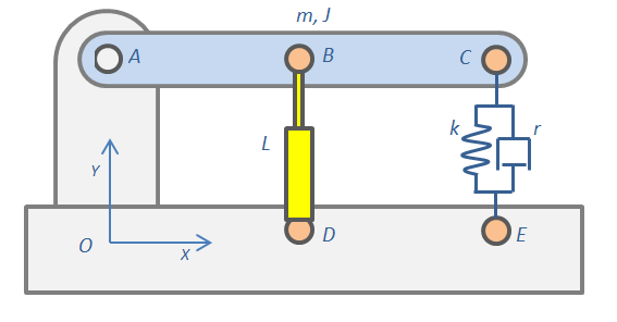
Although Chrono already has methods to define linear actuators, Simulink and its SimHydraulics toolbox are used to produce an advanced model of a hydraulic actuator with valves, piping, pumps, feedback control, etc. The yellow actuator will be simulated in Simulink, the rest in Chrono.

The Simulink model

First, open Simulink and create a model of a hydraulic actuator with a pump and a valve. To keep it simple, just load the Power assisted steering mechanism demo of SimHydraulics (sh_hydraulic_power_assisted_steering.mdl). It includes a ready-to use system where a piston is moved back and forth depending on the feedback control of the rotation of a steering wheel:
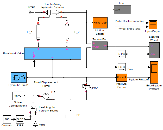
Note that the original example used a mass-spring-damper system modeled with SimScape Simulink blocks; this can be seen by double clicking on the Load block to expand it:
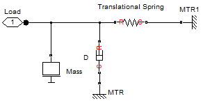
Replacing the Load block with a Chrono mechanical load calls for the following steps:

  • Delete the Load block.
  • Open data/cosimulation/CEcosimulation.mdl, copy the CoSimulate block and paste it into the model, near the piston.
  • Select CoSimulate and use menu Edit/Link Options../Break link so that you can modify it
  • Create the following connections between the piston and the CoSimulate block:
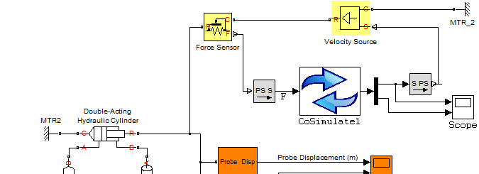
The CoSimulate block is an interface that sends its input vector of variables to Chrono and gets back an output vector at fixed time intervals. Specifically,

  • Simulink sends the force of the piston to Chrono. Chrono will apply that force to the mechanical system between the 'B' and 'D' hinges, so it will compute speed and displacement.
  • Vice-versa: Chrono sends speed & displacement of the piston to Simulink. Simulink will enforce that speed and displacement to the piston so that it will compute the force.

This explains the need for those two yellow blocks: one is the SimScape Simulink block used to get a reaction force (in this example in the rod of the piston) while the other is used to impose a motion (in this example to the rod of the piston). The PS S and S PS grey blocks are used to convert SimScape and SimHydraulics signals from/to Simulink signals.

Note that there could be other ways to do co-simulation for this example. For instance, one could impose a force in Simulink and send displacement information to Chrono, then Chrono imposes displacement with a rheonomic linear actuator and gets the reaction force to send to Simulink.

Double click on the CoSimulate block and set its parameters:
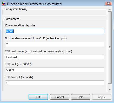
Semantics:

  • Communication step size: controls how frequently Chrono and Simulink exchange information. This example needs a very small step size because this is a stiff problem (as is often the case with hydraulic problems) so larger steps would cause numerical stability issues.
  • N. of scalars received from Chrono must match the number of variables sent from the Chrono-side using C++. In this example what gets sent is 1) velocity and 2) displacement of the rod.
  • TCP host name: leave 'localhost' if you run both simulators on the same computer, otherwise if you have Chrono on a different machine, you provide the IP address here.
  • TCP port: any non-firewalled, non-used port can work here. For instance, use 50009.
  • TCP timeout: if Chrono does not respond within this period, the simulation is stopped.

Next, save the entire model with a proper name. This example already provides a ready-to-use model: data/cosimulation/test_cosim_hydraulics.mdl

The Chrono model

You can find a ready-to-use example in src/demos/cosimulation/demo_COSIM_hydraulics.cpp. The steps implemented in this program are as follows:

  • Use the 'try...catch' statements around socket communication operations because errors in sockets might throw exceptions.
  • Create a Chsystem and populate it with a truss, a moving body, and a revolute joint.
  • Now create create a 'dead' linear actuator between two points using a ChLinkTSDA with zero stiffness and damping. This will be used to apply the force between the two bodies as a cylinder with spherical ball ends.
  • Create a spring-damper to have some load when moving, and configure the system's solver precision.
  • Add a socket framework object (a unique copy to be used through all the program) and a cosimulation interface.
  • Prepare the two column vectors of data that will be swapped back and forth between Chrono and Simulink:
    • receive one variable from Simulink (the hydraulic cylinder force);
    • send two variables to Simulink (the hydraulic cylinder velocity and displacement).
  • Wait for client (Simulink) to connect. Note that in this implementation Chrono is the server and Simulink the client.
  • Upon establishing a connection, the simulation is ready to begin. Note that 'dt' must be the same with the value entered in the CEcosimulation block.
  • Finally, provision for exception catching in running into any trouble with the socket connection.

Run the cosimulation

All the tools are ready for the cosimulation at this point. The next steps:

  • Compile the Chrono program;
  • Run the Chrono program; it will enter a wait state because it is waiting Simulink to connect;
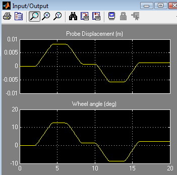
  • Open the ''Input/Output'' orange scope block in Simulink, simply to plot some results.
  • Run the Simulink model by pressing the '>' button in the Simulink interface;

The two codes will run in parallel and will exchange data periodically up to the end of the simulation or up to when one presses 'stop' or aborts the Chrono program.
Notes

Co-simulation can be slow if the communication timestep is small. In some cases a small timestep is unavoidable - in the example discussed here this is necessary because the system is stiff and larger steps would cause a numerical instability that will see the variables oscillating wildly.
One can configure the ''CoSimulate'' block with more than one input and two outputs. For instance, if you are going to simulate six PID controllers for a 6 DOF robot using Simulink, you might need to receive six rotations from Chrono as output and send six control signals (ex. torques) to Chrono, as input of CoSimulate.
Only a single ''CoSimulate'' block can be used at a time. If you need to send/receive a larger number of variables, simply configure the block to have vectors with more elements as input and outputs.
The input and output signals of the 'CoSimulate' block accepts vectors. To build a vector from single signals use the 'Mux' block in Simulink. To split a vector in single signals use a 'De-Mux' block as shown in the example above.
If you have multiple options for choosing where to split a system in two subsystems for cosimulation, keep in mind this rule of thumb: split in a place where the connecting variables (forces, displacements or such) experience 'low frequencies' rather than high frequencies because the higher the frequencies that flow in the interface, the smaller the communication step must be.
Changing the Simulink integrator from variable time step to fixed time step might yield a warning or error about blocks having different sample rates. Use the menu Simulation/Configuration parameters..., go to the Solver tab, then set 'Tasking mode for periodic sample times: SingleTasking' (default is Auto).

The entire code

// =============================================================================
// PROJECT CHRONO - http://projectchrono.org
//
// Copyright (c) 2014 projectchrono.org
// All rights reserved.
//
// Use of this source code is governed by a BSD-style license that can be found
// in the LICENSE file at the top level of the distribution and at
// http://projectchrono.org/license-chrono.txt.
//
// =============================================================================
// Authors: Alessandro Tasora
// =============================================================================
//
// Advanced demo showing how to implement a cosimulation with Chrono and
// Simulink. The SimHydraulics toolbox of Simulink is used here to simulate a
// hydraulic circuit that interacts with a Chrono mechanism.
//
// This example needs test_cosim_hydraulics.mdl to be loaded and run in Simulink
//
// =============================================================================
#include "chrono/physics/ChSystemNSC.h"
#include "chrono/utils/ChSocketCommunication.h"
using namespace chrono;
using namespace chrono::utils;
int main(int argc, char* argv[]) {
std::cout << "Copyright (c) 2017 projectchrono.org\n"
<< "Chrono version: " << CHRONO_VERSION << std::endl;
std::cout << "CHRONO SimHydraulics cosimulation\n" << std::endl;
std::cout << "NOTE! This requires a copy of Simulink with SimHydraulics.\n" << std::endl;
try {
// Test
// Create a cosimulation interface for simulating an hydraulic
// system in Simulink, connected to a mechanical system in
// Chrono::Engine.
// It requires a license of the SimScape/SimHydraulics Matlab toolbox.
// 1) Create a very simple ChronoEngine system, without user interface
// The physical system: it contains all physical objects.
ChSystemNSC my_system;
// Create rigid bodies and add them to the system:
auto my_body_A = chrono_types::make_shared<ChBody>(); // truss
my_body_A->SetFixed(true); // truss does not move!
my_system.AddBody(my_body_A);
auto my_body_B = chrono_types::make_shared<ChBody>(); // moving body
my_body_B->SetMass(114);
my_body_B->SetInertiaXX(ChVector3d(50, 50, 50));
my_body_B->SetPos(ChVector3d(1, 1, 0));
my_system.AddBody(my_body_B);
// Now create a mechanical link (a revolute joint in 0,0,0)
// between these two markers, and insert in system:
auto my_link_BA = chrono_types::make_shared<ChLinkLockRevolute>();
my_link_BA->Initialize(my_body_B, my_body_A, ChFrame<>(ChVector3d(0, 1, 0)));
my_system.AddLink(my_link_BA);
// Now create a 'dead' linear actuator between two points using a ChLinkTSDA with zero stiffness and damping.
// This will be used to apply the force between the two bodies as a cylinder with spherical ball ends.
auto my_link_actuator = chrono_types::make_shared<ChLinkTSDA>();
my_link_actuator->Initialize(my_body_B, my_body_A, false, ChVector3d(1, 0, 0), ChVector3d(1, 1, 0));
my_link_actuator->SetSpringCoefficient(0);
my_link_actuator->SetDampingCoefficient(0);
my_link_actuator->SetRestLength(my_link_actuator->GetLength());
my_system.AddLink(my_link_actuator);
// Create also a spring-damper to have some load when moving:
auto my_link_springdamper = chrono_types::make_shared<ChLinkTSDA>();
my_link_springdamper->Initialize(my_body_B, my_body_A, false, ChVector3d(1, 0, 0), ChVector3d(1, 1, 0));
my_link_springdamper->SetSpringCoefficient(4450);
my_link_springdamper->SetDampingCoefficient(284);
my_link_springdamper->SetRestLength(my_link_springdamper->GetLength());
my_system.AddLink(my_link_springdamper);
my_system.GetSolver()->AsIterative()->SetMaxIterations(20);
// 2) Add a socket framework object
ChSocketFramework socket_tools;
// 3) Create the cosimulation interface:
ChSocketCommunication cosimul_interface(socket_tools,
1, // n.input values from Simulink
2); // n.output values to Simulink
// Prepare the two column vectors of data that will be swapped
// back and forth between Chrono and Simulink. In detail we will
// - receive 1 variable from Simulink (the hydraulic cylinder force)
// - send 2 variables to Simulink (the hydraulic cylinder velocity and displacement)
data_in.setZero();
data_out.setZero();
// 4) Wait client (Simulink) to connect...
std::cout << " *** Waiting Simulink to start... ***\n"
<< "(load 'data/cosimulation/test_cosim_hydraulics.mdl' in Simulink and press Start...)\n"
<< std::endl;
int PORT_NUMBER = 50009;
cosimul_interface.WaitConnection(PORT_NUMBER);
double mytime = 0;
double histime = 0;
// Here the 'dt' must be the same of the sampling period that is
// entered in the CEcosimulation block
double dt = 0.001;
// 5) Run the co-simulation
while (true) {
// A) ----------------- ADVANCE THE Chrono SIMULATION
if (dt > 0)
my_system.DoStepDynamics(dt);
mytime += dt;
// B) ----------------- SYNCHRONIZATION
// B.1) - SEND data
// - Set the Chrono variables into the vector that must
// be sent to Simulink at the next timestep:
// * the velocity of the hydraulic actuator
// * the displacement of the hydraulic actuator
data_out(0) = my_link_actuator->GetVelocity();
data_out(1) = my_link_actuator->GetDeformation();
// std::cout << "Send" << std::endl;
cosimul_interface.SendData(mytime, data_out); // --> to Simulink
// B.2) - RECEIVE data
// std::cout << "Receive" << std::endl;
cosimul_interface.ReceiveData(histime, data_in); // <-- from Simulink
// - Update the Chrono system with the force value that we received
// from Simulink using the data_in vector, that contains:
// * the force of the hydraulic actuator
my_link_actuator->SetActuatorForce(data_in(0));
std::cout << "--- time: " << mytime << std::endl;
}
} catch (std::exception exception) {
std::cerr << " ERRROR with socket system:\n" << exception.what() << std::endl;
}
return 0;
}
virtual std::shared_ptr< ChSolver > GetSolver()
Access the solver currently associated with this system.
Definition: ChSystem.h:124
virtual void AddLink(std::shared_ptr< ChLinkBase > link)
Attach a link to the underlying assembly.
Definition: ChSystem.cpp:144
Representation of a 3D transform.
Definition: ChFrame.h:41
void SetGravitationalAcceleration(const ChVector3d &gacc)
Set the gravitational acceleration vector.
Definition: ChSystem.h:148
void SetSolverType(ChSolver::Type type)
Choose the solver type, to be used for the simultaneous solution of the constraints in dynamical simu...
Definition: ChSystem.cpp:249
int DoStepDynamics(double step_size)
Advance the dynamics simulation by a single time step of given length.
Definition: ChSystem.cpp:1635
Class for socket communication interface.
Definition: ChSocketCommunication.h:34
Chrono core utilities.
Definition: ChBenchmark.h:27
ChVector3< double > ChVector3d
Alias for double-precision vectors.
Definition: ChVector3.h:283
Eigen::Matrix< T, Eigen::Dynamic, 1, Eigen::ColMajor > ChVectorDynamic
Column vector with dynamic size (i.e., with size unknown at compile time).
Definition: ChMatrix.h:112
Main namespace for the Chrono package.
Definition: ChCamera.cpp:17
virtual void AddBody(std::shared_ptr< ChBody > body)
Attach a body to the underlying assembly.
Definition: ChSystem.cpp:132
Class for a physical system in which contact is modeled using a non-smooth (complementarity-based) me...
Definition: ChSystemNSC.h:29
A single object of this class must be instantiated before using all classes related to sockets,...
Definition: ChSocket.h:278