Table of Contents
Motors are objects that can be used to impose a motion, either linear (ChLinkMotorLinear) or rotational (ChLinkMotorRotation), either to 1D (i.e. ChShaft) or 3D objects (i.e. ChBody).
Since ChLinkMotorRotation and ChLinkMotorLinear inherit from ChLinkMate all the considerations made on this latter apply also for these motors.
With some exceptions, the motion is controlled through ChFunction objects, discussed here.
| - | 3D Rotational | 3D Linear | 1D Linear/Rotational |
|---|---|---|---|
| Impose displacement | ChLinkMotorRotationAngle | ChLinkMotorLinearPosition | ChShaftsMotorPosition |
| Impose speed | ChLinkMotorRotationSpeed | ChLinkMotorLinearSpeed | ChShaftsMotorSpeed |
| Apply load | ChLinkMotorRotationTorque | ChLinkMotorLinearForce | ChShaftsMotorLoad |
| Connect to 1D driveline | ChLinkMotorRotationDriveline | ChLinkMotorLinearDriveline | - |
3D Rotational Motors
These motors connect two parts of class ChBodyFrame, i.e objects that have translation+rotation in space, for example ChBody or ChNodeFEAxyzrot.
All rotational motors are inherited from ChLinkMotorRotation and consider a rotation around the Z axes of the constrained frames expressed in radians as base unit.
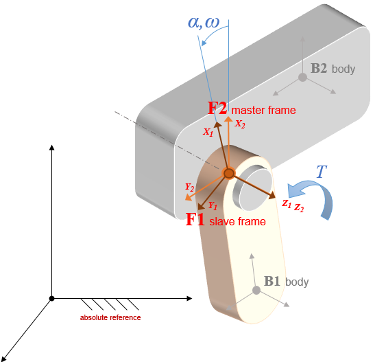
Rotational motors allow multiple turns and offers either the wrapped GetMotorAngleWrapped() or unwrapped GetMotorAngle() motor angle.
Relative displacement|speed|acceleration are retrieved through GetMotorAngle() | GetMotorAngleDt() | GetMotorAngleDt2()
By default, all rotational motors also embed a revolute constraint along the Z axis unless otherwise specified by means of the SetSpindleConstraint() method, that can accept the following options:
- FREE : enforces no constraint on spindle direction/alignment
- REVOLUTE: enforces X,Y,Z, RX, RY constraints (default)
- CYLINDRICAL: enforces X,Y, RX, RY constraints
- OLDHAM: enforces RX, RY constraints
In general, the process of adding a motor involves the following steps:
- Create the motor from the desired ChLinkMotorXxxyyy class
- Use one of the
Initialize()methods available on the class - Add the motor to a ChSystem
- Associate a ChFunction object that describes the motion function; methods names differ depending on the specific derived class.
Example:
3D Linear Motors
These motors connect two parts of class ChBodyFrame, i.e objects that have translation+rotation in space, for example ChBody or ChNodeFEAxyzrot.
All linear motors are inherited from ChLinkMotorLinear and the assume the Z axis being the direction of the allowed direction.
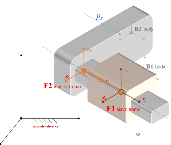
By default, all linear motors also provide a prismatic constraint for the other relative degrees of freedom (translation about Y,Z and rotation about RX, RY, **RZ, except rotation translation Z that is the one controlled by the motor) so you do not need to create additional joints, like ChLinkLockPrismatic for example, to keep the two parts together. Anyway, if you prefer, this behavior can be changed by using the ChLinkMotorLinear::SetGuideConstraint() function, that can accept the following options:
Relative displacement|speed|acceleration are retrieved through GetMotorPos() | GetMotorPosDt() | GetMotorPosDt2()
By default, all linear motors also embed a prismatic constraint along the Z axis, unless otherwise specified by means of the SetGuideConstraint() method, that can accept the following options:
- FREE : enforces no constraint on roller direction/alignment
- PRISMATIC: enforces X, Y, RX, RY, RZ constraints (default)
- SPHERICAL: enforces X and Y constraints
The initialization is similar to the ChLinkMotorRotation case.
3D Driveline Motors
The ChLinkMotorLinearDriveline and ChLinkMotorRotationDriveline allow to impose a relative motion (translational and rotational respectively) between two 3D bodies by coupling it with the translation/rotation of a ChShaft (that, we may remember, could act as either a 1D translational or rotational element). The constrained direction is always along Z.
Because of this coupling any motion imposed on the shaft leads to a consequent motion on the constrained frames (linear or rotational, depending on the motor type), but especially any reaction force/torque felt by the constrained bodies is reflected back to the shaft.
This means that, contrary to the other ChLinkMotors that were fed directly by a "signal" provided through a ChFunction, this class preserve the balance of power and describes a full coupling at both displacement and force level.
Particular care should be put in setting proper values to the inertia of the ChShafts objects to avoid instabilities, especially with low inertias and high speeds.
1D Motors
Motors of the ChShaftsMotor kind are operating on pair of objects of the 1D space.
The usage is similar to those of the ChLinkMotor types with the difference that constrained objects are of the ChShaft type.
Examples
See also: